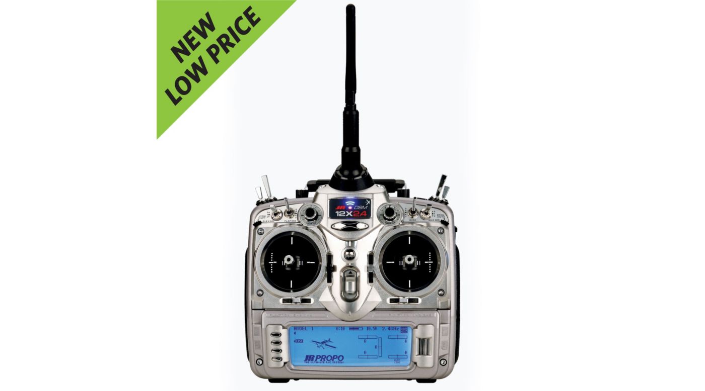
Jr Propo Transmitter Manual
• 7 CHANNEL 2.4GHz DUAL MODULATION SPECTRUM SYSTEM 7 CHANNEL 2.4GHz DUAL MODULATION SPECTRUM SYSTEM Operation Manual Warranty Repair Card Included Prior to use, please read this manual thoroughly. Keep this manual in a convenient place for quick and easy reference. • Thank you for your purchase. As this proportional radio system is a very delicate instrument which is subject to use under vibration and other severe conditions, please read this manual thoroughly before use for your safety. Make sure to especially confirm and follow the GENERAL NOTES &. • GENERAL NOTES & PRECAUTIONS for Safety Make sure to follow the following.
Main tenu samjhawan ki lyrics female version download. Now download videos in all formats from Youtube using GenYoutube video downloader. GenYoutube is a fast Youtube video downloader service.
JR has preprogrammed a variety of useful mixes in the transmitter but they are dedicated to specific channels. If you want the radio to program easily and with maximum flexibility it is best connect your servos to the channels specified in the manual. To keep you interested, the receiver channels are referenced in the manual by a variety of names.
About the Proportional System DANGER Please understand that we cannot be responsible for any accident, Out-of-control and danger can be caused. Failure, etc. That may occur from modification of this product, use of DO NOT use the product on rainy days since it may cause non-genuine parts, natural disaster, or non-observance of the precau- malfunction if water gets inside the transmitter/receiver.
• Rechargeable Battery and Battery Charger DO NOT scratch or tear off the insulating tube, the lead wire, and the connector. Abide by the following to prevent potential leakage, explo- DO NOT use the battery if a scratch is left on the insulat- sion, heat generation, and fire ing tube, lead wire, and connector, or if the insulating is damaged. • Specifications of the Set Transmitter Part No.
XG7(NET-K337G) Operation 7 channels, Computer mixing system system Transmit 2.4GHz band, frequency FH-SS (Frequency hopping system spectrum diffusion) Power supply Dedicated nickel metal-hydride battery 8H1500(1500mA) Consumption 250mA current Neutral 1.5m s Battery Charger Part No. • Transmitter Names and functions of parts Antenna Trainer (Rocker) Switch Hovering Pitch Trim (FOR HELI) Neck Strap Eyelet Flap lever Switch (FOR AIRPLANE) Carrying Bar Rudder Dual Rate Switch Throttle Hold Switch (FOR HELI) Mixing Switch (FOR AIRPLANE) Hovering Throttle Trim (FOR HELI) AUX 2 Lever Switch (FOR AIRPLANE) Flight Mode Switch (FOR HELI) Flap Mixing Switch (FOR AIRPLANE) • Names and functions of parts on the rear side Status LED Trainer Jack Battery Charge Jack Battery Cover When changing the battery, press this cover down to open it. When closing the rear cover, take care not to catch the lead wires between the cover and the case. • How to Set Bind In the situation where this transmitter and receivers are being used after changing the model, and in the situation CAUTION where a new receiver is being used, binding (pairing) must be carried out otherwise the receiver will not operate. On completion of binding, be sure to For the binding method, refer to the items in system mode remove the bind plug. • Connecting and Mounting In the case of HELICOPTER type AUX3 Spare channel Spare channel AUX2 Batteries for receiver Flap channel FLAP Retractable leg GEAR channel RUDD Rudder channel Antenna Caution ELEV Do not cut or bend surplus lengths of the antennas.
Elevator servo A U X 2 AILE. • Connection and Mounting Spare channel AUX3 Spare channel AUX2 Batteries for receiver Pitch channel PIT. Retractable leg GEAR channel RUDD Switch harness Charging connector Rudder servo Antenna ELEV Elevator servo A U X 2 831B AILE A U X 1 GEAR 8ch 2.4GHz RECEIVER RUDD.
• Key Input and Display Dial Turn right/left to select an item ENTER Key and to increase/decrea se the preset value. LIST Key Further, press (click) the dial to decide on the selected item CLEAR Key and to exit the setting state. This changes the display mode. • Input Mode and Functions Normal Screen Mode When the power is switched on, the display will show the tion Mode and System Mode in the following sections.
Normal screen below. In this condition, the dial may be If the transmitter power is switched on while pressing the used to adjust the contrast and to move to the function key, the screen will enter the system mode.